توربین کاپلان
KAPLAN TURBINE
INTRODUCTION: Kaplan-type hydraulic turbine in which the positions of the runner blades and the wicket gates are adjustable for load change with sustained efficiency, it is a purely axial flow turbine with a vertical shaft disposition. Which was designed and developed by the Australian engineer Viktor Kaplan? Kaplan turbine has adjustable runner blades with less number of blades (i.e. 3 to 8 blades). Kaplan turbines are now widely used throughout the world in high-flow, low-head power production.
Victor Kaplan obtained his first patent for an adjustable blade propeller turbine in 1912. But the development of a commercially successful machine would take another decade. Kaplan struggled with cavitations problems, and in 1922 abandoned his research for health reasons.
DIAGRAM

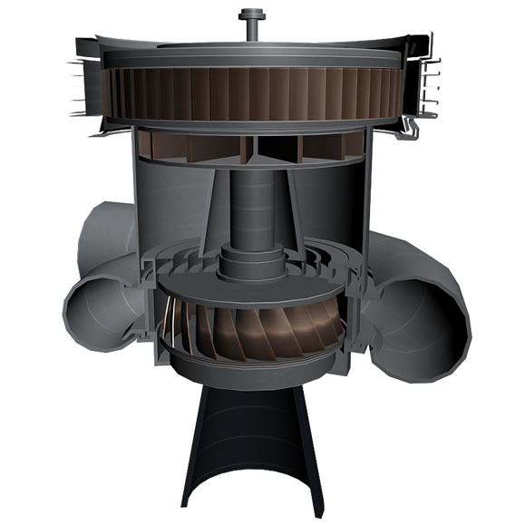
CONSTRUCTION DETAILS OF KAPLAN TURBINE:
Components of the Kaplan turbine:-
· Scroll casing: – It is the cashing in which we pass the water to the runner in the turbine.
· Guide vanes: – It is the blade in which guides the water and control the water passage (i.e. how much the water flow goes in the turbine).
· Draft tube: – After passing through the runner, the water is discharged to the tail race through a gradually expanding tube.
· Runner: – It is an important part of the turbine which is connected to the shaft of the generator and consist movable vanes and hub (boss).
· Hub (Boss):- It is the part of the runner in which blades are mounted.
WORKING OF KAPLAN TURBINE: The Kaplan turbine is an inward flow reaction turbine, which means that the working fluid changes pressure as it moves through the turbine and gives up its energy. The design combines radial and axial features.

The inlet is a scroll-shaped tube that wraps around the turbine’s wicket gate. Water is directed tangentially, through the wicket gate, and spirals on to a propeller shaped runner, causing it to spin.
The outlet is a specially shaped draft tube that helps decelerate the water and recover kinetic energy.
The turbine does not need to be at the lowest point of water flow, as long as the draft tube remains full of water. A higher turbine location, however, increases the suction that is imparted on the turbine blades by the draft tube. The resulting pressure drop may lead to capitation.
Variable geometry of the wicket gate and turbine blades allows efficient operation for a range of flow conditions. Kaplan turbine efficiencies are typically over 90%, but may be lower in very low head applications.
APPLICATIONS: Kaplan turbines are widely used throughout the world for electrical power production. They cover the lowest head hydro sites and are especially suited for high flow conditions.
Inexpensive micro turbines are manufactured for individual power production with as little as two feet of head.
Large Kaplan turbines are individually designed for each site to operate at the highest possible efficiency, typically over 90%. They are very expensive to design, manufacture and install, but operate for decades.
VARIATIONS: The Kaplan turbine is the most widely used of the propeller-type turbines, but several other variations exist:
Propeller turbines have non-adjustable propeller vanes. They are used in low cost, small installations. Commercial products exist for producing several hundred watts from only a few feet of head.
Related posts:
- Lab Manual | FRANCIS TURBINE
- Lab Manual | To study about various types Water Turbines
- LAb Manual | PELTON TURBINE
- Lab Manual | To study about various types Pumps
- Lab Manual | Principle of working of CENTRIFUGAL PUMP


 وبلاگ همه چیز درباره نیروگاه وبلاگی تخصصی درباره نیروگاه است که به صورت تخصصی به مطالب مرتبط با نیروگاه اعم از مکانیک, ابزاردقیق والکتریک میپردازد